The TEst stand for X-band (TEX) framework is based on X-band sources to power two test stations used to validate accelerating structures and C-band source to power Fringe C-band linac used not only for testing radiofrequency structures but also different samples under specific conditions of beam line.
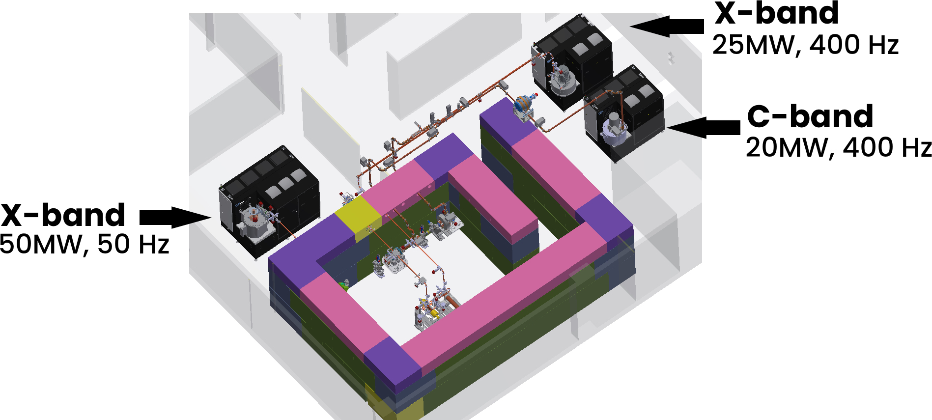
TEX facility layout (bunker internal view) and power sources description
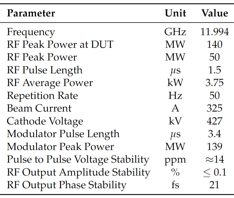
X-band source at 140 MW
X-band radiofrequency (11.994 GHz) at 50 MW is realized with a Scandinova k-400 solid-state pulsed modulator capable of producing high-voltage pulses at 50 Hz of repetition rate. This modulator feeds a 50 MW peak power with a pulse length of 1.5 µs using CPI X-band klystron (model VKX-8311A) driven by a commercial Low-Level radiofrequency system (LLRF) adapted to X-band through an up/down conversion crate. The waveguide network characterized by high vacuum system (pumping units connected to getter and ion pumps) transports the RF power inside the bunker along the device under test (DUT). Considering the waveguide dissipation and using the BOC pulse compressor at the klystron output, the RF signal is compressed to 300 ns and the available maximum peak power at the DUT input is approximately 140 MW. The TEX X-band 50MW source main parameters are reported in the following table.
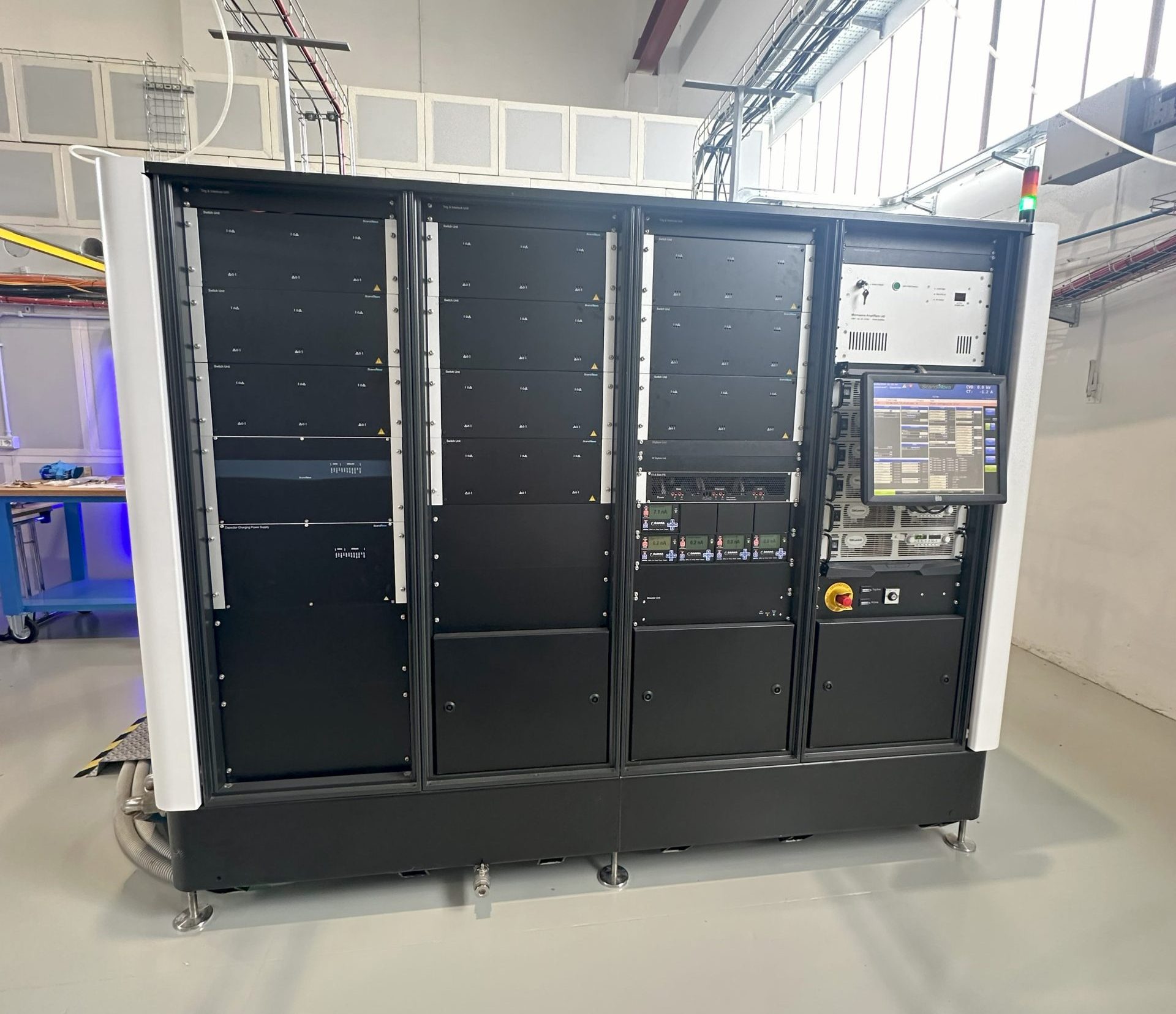
Scandinova k-400 solid-state modulator

CPI X-band klystron
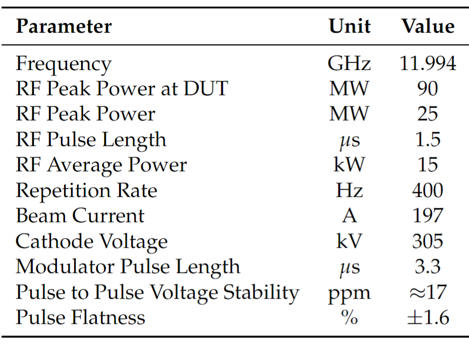
X-band source at 90 MW
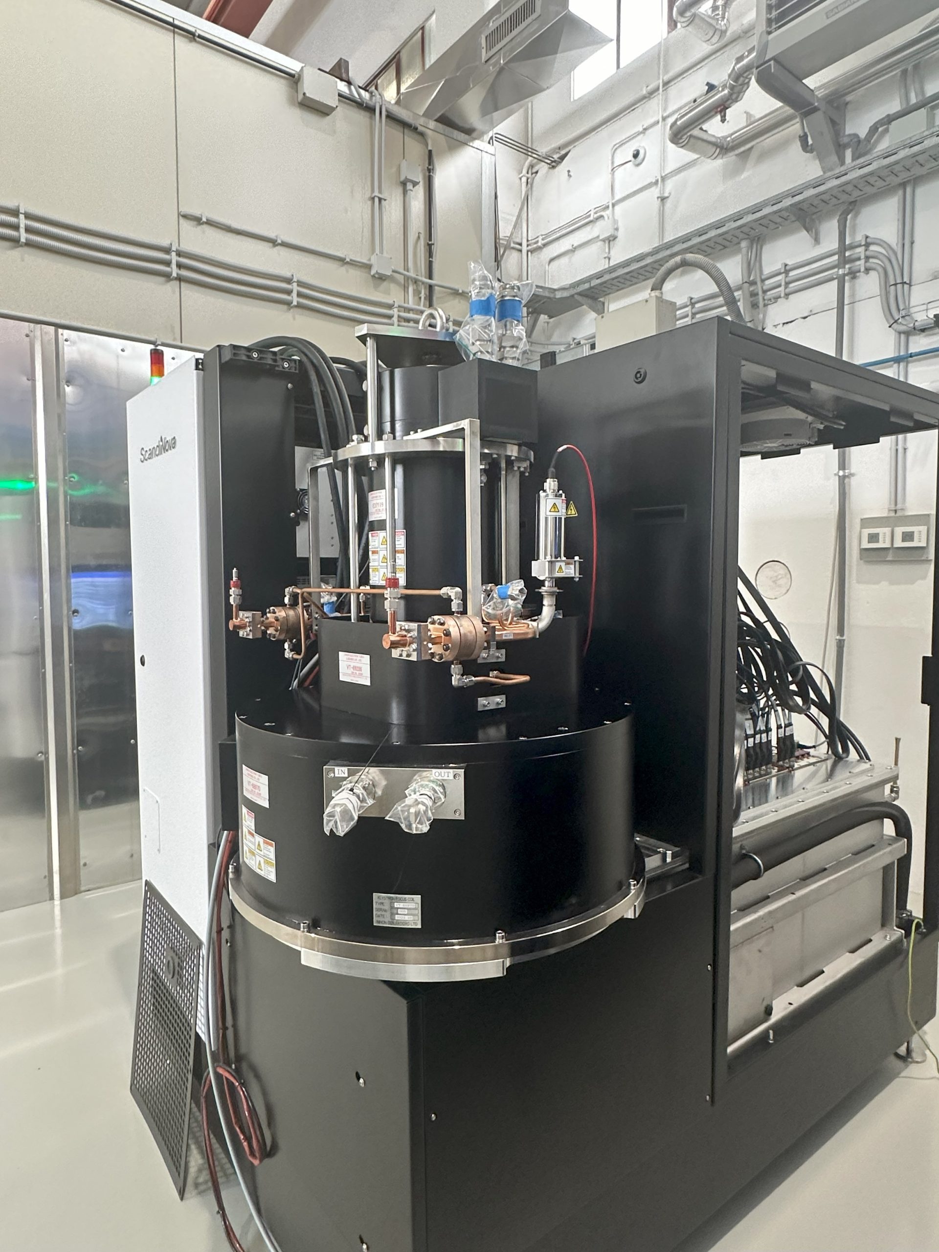
X-band radiofrequency (11.994 GHz) at 25 MW is realized with a Scandinova k-300 solid-state pulsed modulator shown in Fig. 1 capable of producing high-voltage pulses at 400 Hz of repetition rate. This modulator feeds a 25 MW peak power with a pulse length of 1.5 µs using Canon X-band klystron (model E37119) shown in Fig.2 driven by a commercial Low-Level radiofrequency (LLRF) system adapted to X-band through an up/down conversion crate. The waveguide network characterized by high vacuum system (pumping units connected to getter and ion pumps) transport the RF power inside the bunker along the device under test (DUT). Considering the waveguide dissipation and using the BOC pulse compressor at the klystron output, the RF signal is compressed to 300 ns and the available maximum peak power at the DUT input is approximately 90 MW. The TEX X-band 25 MW source main parameters are reported in the following table.
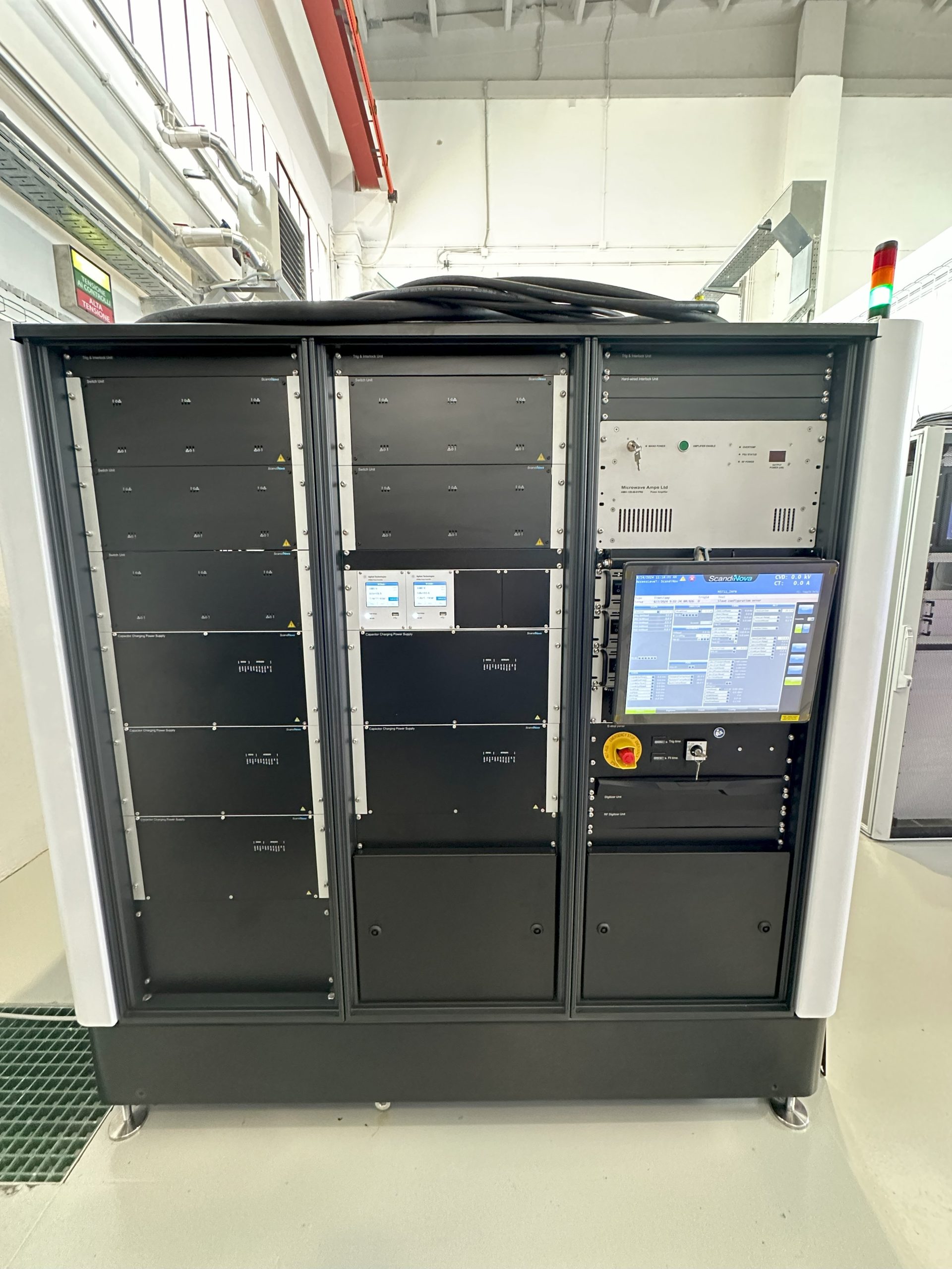
Scandinova k-300 solid-state modulator
Canon X-band klystron
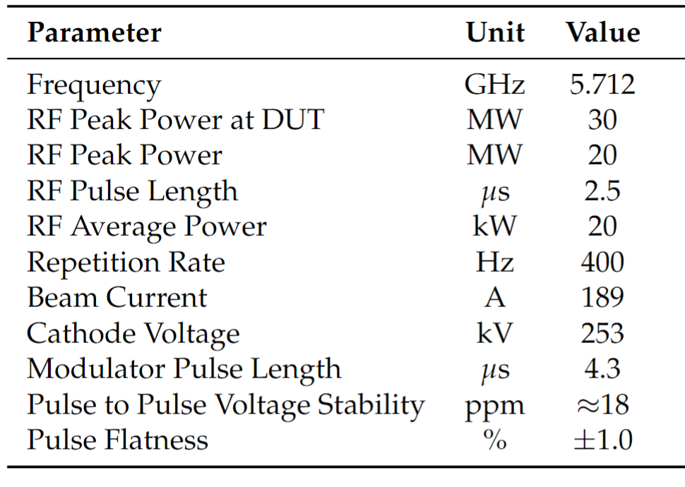
C-band source at 30 MW
C-band radiofrequency (5.712 GHz) at 20 MW is realized with a ScandiNova k-300 solid-state pulsed modulator shown in Fig. 1 capable of producing high-voltage pulses at 400 Hz of repetition rate. This modulator feeds a 20 MW peak power with a pulse length of 1.5 µs using Canon C-band klystron (model E37117) shown in Fig.2 driven by a commercial Low-Level radiofrequency (LLRF). The waveguide network characterized by high vacuum system (pumping units connected to getter and ion pumps) carry the RF signal inside the bunker along the high gradient C-band photo-injector for Fringe linac and the device under test (DUT). Considering the waveguide dissipation and using the BOC pulse compressor at the klystron output, the RF signal is compressed to 300 ns and the available maximum peak power at the C-band Gun is 23 MW and at the DUT input is approximately 30 MW. The TEX C-band 20 MW source main parameters are reported in the following table.
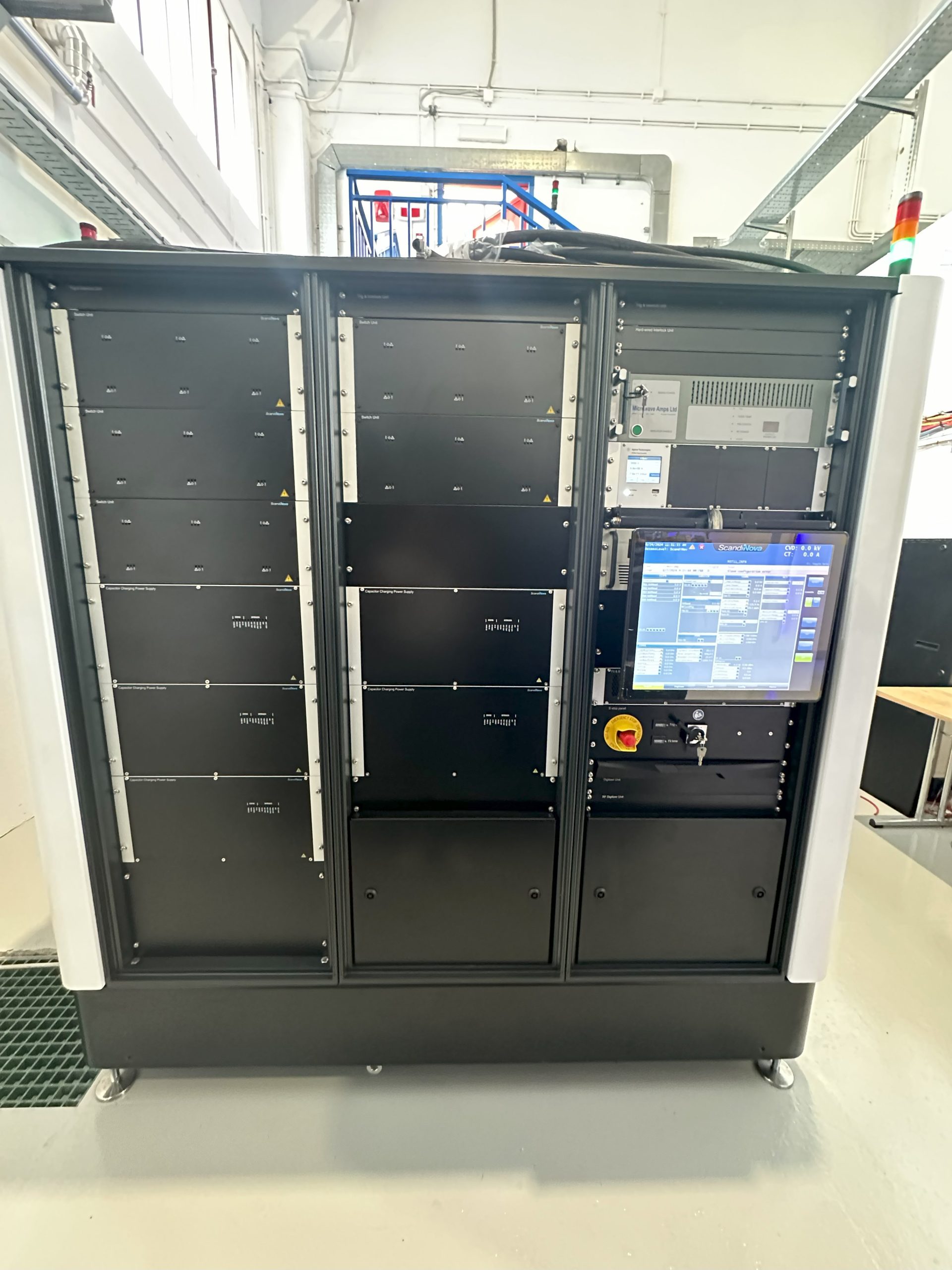
Scandinova k-300 solid-state modulator

Canon C-band klystron
Fringe
Fringe is a C-band (5.712 GHz) electron linac characterized by high repetition rate (400 Hz). The accelerator layout and its main parameters are reported following. The TEX facility becomes a useful test stand that makes a high-brightness electron beam available to external users, private or public institutions. Fringe can study the feasibility of C-band high brightness injectors and electron detectors. Furthermore, the electron beam is made available to study biological samples or electronic devices, allowing the effects of the radiation produced on them and leading the way to future medical accelerators.

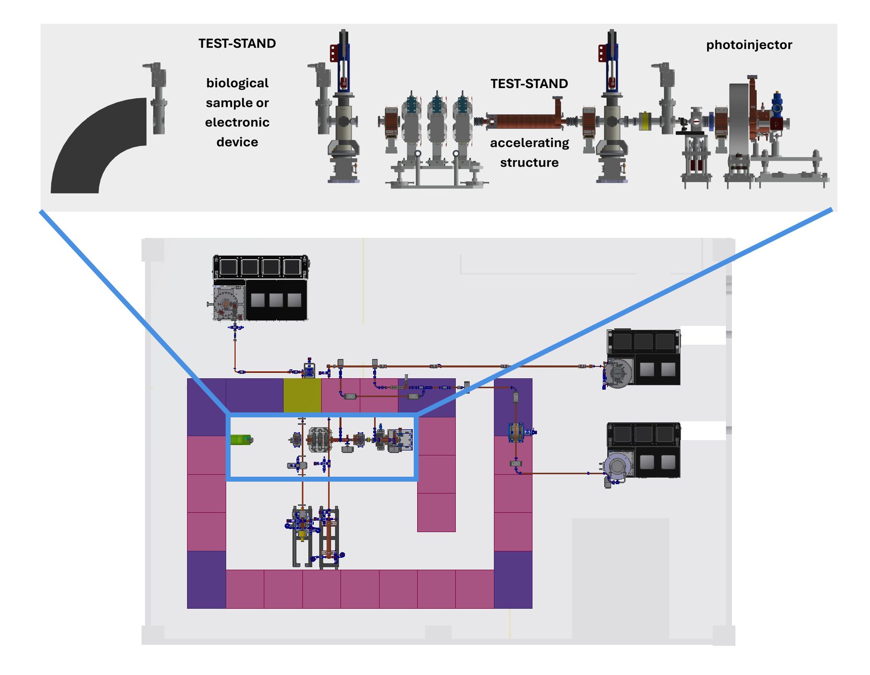
Fringe Linac layout and test-stands available on the beam line